True cost savings from 3D prototyping are not found in the price-per-part, but in strategically de-risking the expensive transition to mass production tooling.
- Success depends on mastering the translation of prototype performance (e.g., FDM) into final part reality (e.g., injection molding).
- Designing for tolerance compensation and mapping failure modes early are more critical than achieving perfect visual accuracy.
Recommendation: Shift your focus from simply printing faster to mastering the engineering discipline of “prototype-to-production translation” to unlock maximum speed and cost efficiency.
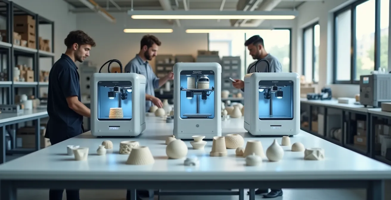
For R&D engineers and product designers, the promise of 3D printing is tantalizing: accelerate innovation, slash costs, and compress development cycles. The common narrative suggests that replacing slow, expensive traditional prototyping with rapid, in-house additive manufacturing is a direct path to a 50% cost reduction. However, experienced teams know the reality is more complex. The true cost of development isn’t in the prototype itself, but in the multi-thousand-dollar tooling error discovered just before a product launch, an error the initial prototype failed to predict.
Many guides focus on the obvious benefits—faster iterations and lower part costs. They discuss choosing between FDM and SLA or the importance of material selection. But they often miss the most critical point. The fundamental challenge and greatest opportunity for cost savings lie in the prototype-to-production translation. An FDM prototype will never behave like an injection-molded part, so how can an engineer reliably use one to validate the other? The key is not to chase a perfect 1:1 material match, but to master the art of interpreting a prototype’s behavior to accurately forecast the performance of the final manufactured product.
This guide moves beyond the basics. We will dissect the strategic engineering decisions that enable you to de-risk your entire development process. We’ll explore how to map failure modes between different manufacturing methods, design for assembly despite inherent tolerance gaps, and decide when to escalate fidelity from a simple 3D print to a more representative silicone mold. By focusing on these critical translation points, you can truly accelerate development and prevent the costly downstream failures that erode any initial savings.
text
This article provides a technical framework for leveraging rapid prototyping to its full strategic potential. Explore the key decision points that separate amateur iteration from professional, cost-effective product development.
Summary: How Rapid Prototyping With 3D Printing Cuts Development Costs by 50%?
- Why a 3D Printed Prototype Fails Under Stress Where Molded Parts Succeed?
- How to Choose the Right SLA or FDM Printer for Your Office?
- Subtractive or Additive: Which Method Mimics Final Production Best?
- The Tolerance Oversight That Makes Prototypes Impossible to Assemble
- When to Move From 3D Printing to Silicone Molds for Beta Testing?
- How to Reduce Your BOM Cost by 15% Without Sacrificing Quality?
- How to Permit a 3D Printed Structure With Local Authorities?
- Mass Production Strategies: Offshoring vs Local Manufacturing for Startups?
Why a 3D Printed Prototype Fails Under Stress Where Molded Parts Succeed?
The most dangerous assumption in rapid prototyping is that a 3D printed part will behave identically to its injection-molded or machined counterpart. This oversight leads to false positives in testing and costly tooling redesigns. The core issue lies in the fundamental difference in material structure. An injection-molded part is isotropic, meaning its material properties are uniform in all directions. In contrast, most 3D printed parts, particularly from Fused Deposition Modeling (FDM), are anisotropic.
The layer-by-layer fabrication process of FDM creates inherent weaknesses. The bonds between layers are significantly weaker than the continuous extrusion within a single layer. In fact, research demonstrates that FDM parts exhibit 10-50% weaker strength along the Z-axis compared to the X-Y axes. This means a prototype that withstands a torsional load when printed flat might snap instantly if the force is applied perpendicular to its layers. A successful prototyping strategy doesn’t ignore this; it maps it. For example, a layer separation failure in an FDM part can indicate a potential weld line weakness in the final molded part, prompting a CAD reinforcement before any tooling is cut.
Different technologies present different failure modes. While SLA produces visually stunning parts with excellent detail, the standard resins are often brittle and unsuitable for functional testing requiring impact resistance. SLS parts are stronger but can have porosity that initiates fractures. The goal isn’t to find a prototype that *is* the final part, but one whose failure modes are well-understood and can be translated into actionable design insights for the final production method. This is the first principle of effective prototype-to-production translation.
How to Choose the Right SLA or FDM Printer for Your Office?
Bringing prototyping in-house is a key step to accelerating development, but selecting the right technology requires looking beyond the printer’s price tag. The decision between a workhorse FDM machine and a high-resolution SLA printer should be driven by a Total Cost of Workflow analysis, not just the initial investment. This includes accounting for ventilation, post-processing equipment, material costs, and staff training time.
SLA printers, for example, require dedicated wash and cure stations, which can add over $1,000 to the setup. They also use resins that necessitate a well-ventilated area for fume extraction, a factor often overlooked in a standard office environment. FDM is generally more forgiving in this regard. Furthermore, the learning curve and failed print rate impact the true cost-per-part and iteration velocity. While SLA can produce a part faster, the multi-step post-processing can negate that speed advantage for quick, low-fidelity form checks where FDM excels.
This table outlines the hidden operational factors that influence the real cost and efficiency of each ecosystem.
| Factor | FDM | SLA |
|---|---|---|
| Initial Investment | $2,000-$8,000 (professional) | $4,500-$10,000 (mid-range) |
| Ventilation Requirements | Minimal | Essential (fume extraction) |
| Post-Processing Equipment | Basic tools | Wash/cure stations ($500-$1,500) |
| Staff Training Time | 1-2 days | 3-5 days |
| Failed Print Rate (learning curve) | 10-15% | 15-20% |
| Iteration Velocity (full cycle) | 4-8 hours | 2-6 hours |

Ultimately, the investment decision should be based on a breakeven analysis. Depending on your part volume and complexity, an in-house desktop printer can pay for itself within months. As an analysis of rapid prototyping workflows shows, the real saving is measured in the weeks or months of lead time eliminated over a project’s lifecycle. Choose the system that best matches your primary use case, whether it’s rapid form/fit tests (FDM) or high-detail visual models (SLA).
Subtractive or Additive: Which Method Mimics Final Production Best?
The prototyping fidelity question extends beyond just FDM versus SLA; it encompasses the broader choice between additive and subtractive (CNC machining) methods. No single process is universally “best.” The optimal choice depends entirely on which aspect of the final product you need to validate. This is where the concept of a Fidelity Spectrum becomes a crucial strategic tool. Instead of asking “is this a functional prototype?” ask “what function am I testing?”
If you need to mimic the surface finish of a final injection-molded part for an important stakeholder review, SLA is unparalleled, achieving up to 95% fidelity. However, if you are testing the mechanical properties of a future metal part, nothing beats CNC machining a prototype from the actual production material, offering 100% material property matching. Additive methods like SLS or FDM shine where subtractive methods fail, such as creating parts with complex internal channels for cooling or fluid flow.
A hybrid workflow often yields the best results. One successful approach saw a design team reduce their design cycle by 40% and save over £3,000 in tooling revisions. They used high-resolution SLA prototypes for user testing and visual approval, leveraging the smooth finish to get stakeholder buy-in. Concurrently, they used durable FDM prints from ABS to test bracket placement, structural rigidity, and the stress of repeated assembly/disassembly. This dual-track approach allowed them to validate different aspects of the design with the most appropriate and cost-effective method.
| Production Aspect | Best Method | Fidelity Level |
|---|---|---|
| Surface Finish (Injection Molding) | SLA | 90-95% |
| Mechanical Properties (Metal) | CNC Machining | 95-98% |
| Complex Internal Channels | 3D Printing (SLS/FDM) | 100% |
| Dimensional Tolerances | CNC + SLA Hybrid | 98% |
| Material Properties Match | CNC (same material) | 100% |
| Assembly Fit Testing | SLA or High-end FDM | 85-90% |
The Tolerance Oversight That Makes Prototypes Impossible to Assemble
A prototype that looks perfect but cannot be assembled with its mating parts is a worthless prototype. One of the most common and costly oversights in rapid prototyping is failing to design for the inherent dimensional variance of different 3D printing technologies. While engineers are accustomed to the tight tolerances of CNC machining, the additive world operates with a different set of rules. A design that works on paper may result in a tolerance stack-up that makes assembly impossible.
The precision varies significantly by technology. According to precision testing, SLA can achieve tight tolerances of ±0.05 mm, making it ideal for fit testing. In contrast, a typical FDM printer operates in the ±0.2-0.5 mm range. This variance, especially the greater inaccuracy in the Z-axis due to layer height, must be actively compensated for in the CAD model. Simply exporting the final production design and hitting “print” is a recipe for failure.
A proactive Design for Post-Processing strategy is essential. This involves designing sacrificial surfaces on critical mating interfaces that can be post-machined to final tolerance, or building in compliance features like flexible tabs and lead-in chamfers that accommodate variance. This anticipates and solves assembly problems at the design stage, rather than discovering them with a physical part in hand.
Action Plan: Implementing a Design for Tolerance Strategy
- Sacrificial Surfaces: Add 0.2-0.3mm of extra material to critical mating interfaces intended for post-machining to achieve final tolerance.
- Asymmetric Tolerances: In your CAD, design specifically for FDM by allowing +0.1mm variance in the Z-axis and a tighter +0.05mm in the X-Y plane.
- Self-Alignment Features: Include pilot pins with 15° lead-in chamfers and corresponding holes to guide parts into correct alignment during assembly automatically.
- Compliance by Design: Implement flexible tabs approximately 0.5mm thick in non-critical areas to absorb a ±0.2mm variance in fit.
- Graduated Press-Fits: For parts that must be press-fit, design a graduated series of test features, starting with a loose 0.3mm clearance and tightening to a 0.05mm interference fit to find the optimal value.
When to Move From 3D Printing to Silicone Molds for Beta Testing?
While in-house 3D printing is unmatched for early-stage iteration, there comes a point where its material limitations yield diminishing returns, especially for beta testing. When you need feedback on the “production feel” of a product, a standard 3D printed prototype can be misleading. A brittle SLA part or a rough FDM print doesn’t accurately represent the aesthetics, weight, and durability of a final injection-molded product. This is the strategic inflection point to transition from 3D printing to urethane casting using silicone molds.
This “soft tooling” approach involves 3D printing a master pattern, finishing it to a high-quality surface, and then creating a silicone mold from it. This mold can then be used to cast 20-50 high-fidelity copies in production-grade urethane plastics. This method provides parts with material properties that are reportedly 85% closer to final injection-molded plastics, compared to just 40% for typical 3D printing materials. The feedback gathered from beta testers using these parts is far more reliable for evaluating critical aspects like snap-fit durability and perceived quality.
The financial justification is compelling. While creating a silicone mold can cost around $1,000, it serves as a crucial insurance policy against a much larger risk. A cost-benefit analysis reveals that a single tooling mistake can cost upwards of $50,000 to correct, giving the soft tooling stage a potential ROI of 50:1. It’s a small investment to validate a design with high fidelity before committing to expensive and difficult-to-change steel tooling. This step is the bridge between rapid iteration and de-risked mass production.
How to Reduce Your BOM Cost by 15% Without Sacrificing Quality?
Beyond preventing errors, additive manufacturing offers powerful tools to proactively reduce the Bill of Materials (BOM) cost without compromising quality. The primary mechanism is part consolidation. Traditional manufacturing methods often require complex assemblies of multiple brackets, fasteners, and components. With the design freedom of 3D printing, a 5- to 10-part assembly can often be redesigned into a single, complex, and more structurally integral component. This not only eliminates the cost of the consolidated parts but also drastically reduces assembly time and labor costs.
This design freedom allows for the integration of features impossible with traditional methods, such as internal passages for wiring or conformal cooling channels that improve performance. For instance, Ford Motor Company has used this approach to achieve a 50% reduction in prototyping costs and a 25% decrease in development time on certain projects. By consolidating parts, they reduce weight, lower assembly costs, and increase structural integrity simultaneously.
Another powerful strategy is rapid material testing. Instead of relying solely on material data sheets, teams can 3D print standardized test specimens—or even sections of the actual part geometry—in proposed cheaper materials. These can be subjected to load, fatigue, and environmental testing within 24 hours. This empirical data allows engineers to confidently switch to a lower-cost material by proving it meets performance requirements in the real-world application, not just in theory. Combining this with topology optimization software, which can identify 20-30% material reduction opportunities in a design, creates a fast and reliable pathway to a leaner, more cost-effective BOM.
How to Permit a 3D Printed Structure With Local Authorities?
While most rapid prototyping occurs at the product scale, the principles of using physical models to communicate intent and de-risk projects apply even at the architectural and construction scale. Getting a building permit for a structure utilizing novel, 3D printed components presents a significant challenge, as building codes often lack specific provisions for these new materials and methods. The key to navigating this regulatory ambiguity is proactive communication and empirical data, using the prototype itself as the primary tool of persuasion.
Architects are finding that detailed, high-fidelity scale models are a powerful communication device. Where 2D drawings can be abstract and difficult for planning commissions to interpret, a physical 3D printed model makes complex structures tangible. Some firms have reported that 1:50 scale models are three times more effective than traditional drawings at securing project approvals. The model ceases to be just a visual aid and becomes a critical piece of the regulatory submission package.
To overcome code ambiguity, a successful strategy involves several key actions. First, provide empirical safety data by creating and destructively testing full-scale structural element samples. This demonstrates performance in a way that calculations alone cannot. Second, reference analogous standards, such as those for pre-cast concrete, to provide a baseline for performance metrics. Engaging authorities early with prototype demonstrations, documenting material properties through certified third-party labs, and building a coalition with local engineering associations can help build the case for equivalency and pave the way for approval.
Key Takeaways
- Anisotropic Weakness: FDM 3D prints are inherently weaker along the Z-axis; this must be accounted for in design and print orientation.
- Total Cost of Workflow: Choose an in-house printer based on the full ecosystem cost, including post-processing, ventilation, and training—not just the initial price.
- Hybrid Fidelity: Use the right tool for the job. Combine high-resolution SLA for visual models with durable FDM or CNC for mechanical tests to optimize cost and time.
Mass Production Strategies: Offshoring vs Local Manufacturing for Startups?
For startups, rapid prototyping’s final and most strategic role is to inform the crucial decision between offshoring and local manufacturing for mass production. Additive manufacturing provides the flexibility to validate both paths simultaneously before committing significant capital. A Design for Manufacturing (DfM) validation strategy involves creating two distinct design paths: Path A is optimized for low-skilled assembly using standard components, ideal for offshoring. Path B leverages part consolidation and complex geometry, designed for local, automated additive manufacturing.
By prototyping both versions in-house, a startup can gather real-world data on assembly time, quality, and durability for each approach. This empirical evidence replaces guesswork with hard numbers, allowing for a data-driven decision on the best production strategy based on projected volume and market conditions. This flexibility is a massive competitive advantage, enabling a pivot if one strategy proves more costly or slower than anticipated.
Furthermore, additive manufacturing enables a powerful “bridge manufacturing” strategy. Instead of waiting months for offshore tooling to be produced, companies can use technologies like SLS or Multi Jet Fusion to manufacture the first 100 to 1,000 units locally. This gets the product to market faster, generates early revenue, and captures initial market feedback while the traditional supply chain is being established. This approach can dramatically reduce tooling expenses—PepsiCo famously achieved 96% cost savings on prototype tooling by using 3D printing. It transforms 3D printing from a simple prototyping tool into a strategic production asset.
To truly accelerate your development cycle and realize the full cost-saving potential of additive manufacturing, start implementing these strategic prototyping frameworks today and transform your path from design to production.